
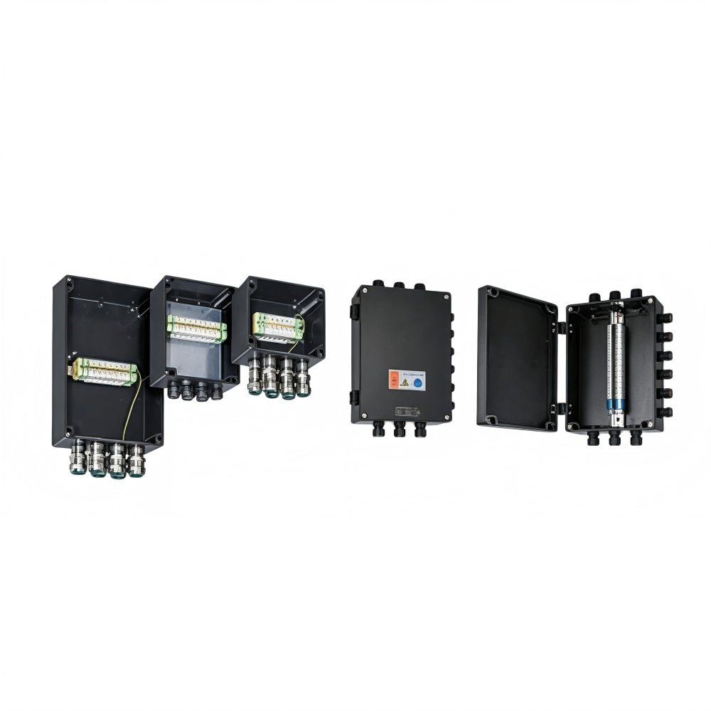
Answer first:A Zone 1 junction box cannot be selected by enclosure size or IP rating alone. The complete specification must match the area classification, required EPL or category, protection concept, gas group, temperature limits, electrical design, cable entries, environmental exposure and destination-market documentation.
Under the EU workplace zoning definition, Zone 1 is a place where an explosive atmosphere consisting of air and flammable gas, vapour or mist is likely to occur occasionally in normal operation. Combustible-dust locations use Zones 20, 21 and 22, not Zone 1.
The following checklist is intended to improve the information supplied to a competent designer or supplier.
1. Confirm the area classification
Start with the project’s approved hazardous-area classification drawing or dossier. Confirm that the location is genuinely Zone 1 and identify the substance responsible for the hazard.
Do not convert a general statement such as “petrochemical area” into a zone by assumption.IEC 60079-10-1addresses classification where flammable gas or vapour hazards may arise. Dust and hybrid-mixture hazards require separate consideration.
2. Define the required EPL, category and market scheme
Zone information must be translated into the equipment protection requirement used by the applicable code or regulation. Record the required Equipment Protection Level, ATEX category where relevant, and any national approval requirement.
“Suitable for Zone 1” is not a complete purchasing specification.
3. Select the correct type of protection
Junction and terminal boxes may use different explosion-protection concepts. Two common examples are:
- Ex d, flameproof enclosure:designed and tested to withstand an internal explosion and prevent flame propagation through specified flamepaths.
- Ex e, increased safety:applies measures intended to prevent arcs, sparks and excessive temperatures in normal service and specified abnormal conditions.
These concepts are not interchangeable. The design, terminals, cover, joints, entries and installation rules must match the protection concept shown in the product documentation.
4. Match the gas group
Identify the gas or vapour and the equipment group or subgroup required by the site assessment. Equipment marked for one subgroup may not be suitable for a more demanding subgroup.
Do not choose a gas group from industry type alone. Use the substance data and applicable classification documentation.
5. Check temperature class and ambient range
The equipment’s temperature classification or maximum surface temperature must be appropriate for the ignition characteristics of the hazardous substance.
Also check the certified ambient range. A standard catalogue ambient range should not be assumed to cover direct sun, process heat, sub-zero weather or an enclosed hot location. Internal power dissipation and terminal loading can also affect temperature.
6. Define the electrical and terminal duty
Provide:
- System voltage and frequency
- Maximum current
- Number and type of circuits
- Terminal quantity and conductor cross-section
- Conductor material
- Protective-earth requirements
- Short-circuit or fault information where applicable
- Heat-producing internal devices, if any
The available internal space is not the only design limit. Creepage, clearance, terminal loading, conductor bending space and heat rise must be evaluated under the applicable design rules.
7. Choose enclosure material for the real environment
Metal, GRP and polycarbonate enclosures have different advantages and constraints. Consider:
- Chemical and salt exposure
- Corrosion
- UV and outdoor weathering
- Impact risk
- Static-charge precautions
- Weight and mounting support
- Cleaning agents
- Operating temperature
- Required earthing or bonding arrangements
A material described as corrosion resistant is not automatically compatible with every chemical. Obtain a compatibility review where exposure is significant.
8. Treat IP protection as a separate requirement
IEC 60529classifies ingress protection provided by enclosures. An IP code describes protection against access, solid objects and water under defined tests; it does not by itself establish explosion protection.
Specify the IP level required by the installation, but verify both the Ex marking and IP marking on the complete equipment.
9. Engineer every cable entry
For each entry, define:
- Cable type and construction
- Armoured or unarmoured cable
- Actual cable outside diameter
- Entry thread and size
- Gland protection concept and certification
- Sealing requirements
- Environmental seal
- Required stopping plugs or blanking elements
Glands, reducers, adapters and stopping plugs must be compatible with the enclosure, protection concept and cable. Unauthorised drilling or substitution can compromise the certified design.
10. Verify earthing and bonding
Confirm internal and external protective-conductor provisions, terminal sizes and bonding requirements. Non-metallic enclosures may still contain metallic entries or devices requiring appropriate bonding.
Follow the manufacturer’s instructions and the applicable installation standard rather than relying on enclosure material as the sole guide.
11. Plan mounting, access and inspection
Check mounting orientation, support, cover-opening clearance, conductor access, condensation management where permitted, and safe maintenance space.
Installation should not place stress on cable entries or damage joints and flamepaths. Future inspection must be possible without creating new hazards.
12. Review marking and documents before approval
Request and check:
- Model-specific datasheet and drawing
- Complete Ex marking
- Applicable certificate or declaration
- Certificate schedule and conditions of use
- Installation and maintenance instructions
- Terminal and cable-entry schedule
- Bill of materials for configured assemblies
- Current document revision
- Traceability information
IEC 60079-14:2024covers installation design, equipment selection, installation and initial inspection.IEC 60079-17:2023addresses inspection and maintenance of hazardous-area electrical installations.
Information to send with an enquiry
A useful request states: destination country, zone, EPL or category, gas group, temperature class, ambient range, IP requirement, enclosure environment, circuit and terminal schedule, cable list, gland requirements, quantity and required certification documents.
This is more reliable than asking only for “a Zone 1 explosion-proof box.”
Request a model-specific review
Review MMAIATEX’sExd/Exe components, glands and boxesand submit the full application data through thecontact page. Ask for current model-specific drawings and documentation before approval.
Safety notice:This checklist does not perform an area classification or certify equipment suitability. Selection, assembly, installation, initial inspection and maintenance must be handled by competent persons under current local regulations, applicable standards, product certificates and manufacturer instructions. Do not modify an Ex enclosure or cable-entry arrangement without documented authorisation.