
What intrinsic safety entity parameters describe
Intrinsic safety controls electrical energy in circuits exposed to an explosive atmosphere. IEC 60079-11:2023 covers intrinsically safe apparatus and associated apparatus connected to those circuits. Its official page is marked Corrected Version 2026-07 and incorporates the listed corrigenda and interpretation sheets through July 2026.
IEC 60079-25:2020+AMD1:2025 CSV addresses the design, construction and assessment of the complete intrinsically safe electrical system. This distinction matters. A certified field device and a certified barrier do not automatically form an acceptable loop when connected.
The entity concept expresses maximum source outputs and maximum receiver inputs. It also limits how much external capacitance and inductance can be connected. The exact values must come from the current certificate schedule, control drawing or manufacturer instructions for the exact terminal set and model suffix.
The five first-screen comparisons
| Source output | Field input or external load | First-screen rule | Evidence needed |
|---|---|---|---|
| Uo | Ui | Uo must not exceed Ui | Exact output and input terminal data |
| Io | Ii | Io must not exceed Ii | Exact source characteristic and receiver limit |
| Po | Pi | Po must not exceed Pi | Current certificate or control-drawing values |
| Co | Ci plus cable capacitance | Total external capacitance must not exceed Co | Every device contribution, cable data and actual length |
| Lo | Li plus cable inductance | Total external inductance must not exceed Lo | Every device contribution, cable data and actual length |
Uo, Io and Po belong to the source or associated-apparatus side of the defined intrinsically safe circuit. Ui, Ii and Pi are input limits for the receiving apparatus. Co and Lo are the permitted external capacitance and inductance under the stated conditions. Ci and Li represent apparatus contributions that must be combined with the cable and other connected equipment.
Do not transfer values between terminal groups. A multi-channel barrier can have different data for each channel or connection mode. A value for one gas group, output characteristic or installation condition may not apply to another.
Why cable capacitance and inductance matter
The cable is part of the energy assessment. Obtain controlled capacitance and inductance data per unit length, confirm the installed or maximum design length and include the contributions required by the project method. Add the field apparatus values and any other connected equipment.
A convenient catalogue cable value is not enough when the project specification, tolerance, screen arrangement or installation method requires another basis. If the installed route can grow during commissioning, assess the controlled maximum length rather than the first drawing estimate.
Mixed capacitance and inductance deserve special care. The full standard, certificate or control drawing can impose a more restrictive combined condition than independently using the maximum Co and maximum Lo. Do not assume that both headline maxima can always be used at the same time.
A practical matching sequence
1. Freeze the topology and identities
List every associated apparatus output, field apparatus input, junction, cable and relevant earth or screen connection. Record legal manufacturer, complete model, suffix, certificate issue and terminal designation.
2. Confirm the hazardous-area basis
Match the required equipment group, intrinsic-safety level and EPL, gas or dust application, temperature information and ambient range. The MMAIATEX EPL guide explains why one parameter pair cannot replace the full protection-level decision.
3. Collect controlled entity data
Retrieve Uo, Io, Po, Co and Lo for each defined source output. Retrieve Ui, Ii, Pi, Ci and Li for every receiver. Also capture Um, Lo/Ro or other conditions when they appear. IECEx OD 017 Edition 7.0 identifies entity parameters and recommends a control drawing to consolidate connection and installation information.
4. Add cable and connected-device energy storage
Calculate the total external capacitance and inductance using the project-approved cable parameters and length. Include all connected contributions that the assessment method requires.
5. Run the first screen
Check the three source-to-input inequalities and the two external energy-storage limits. Record units and source-document revisions. A bare spreadsheet result without document traceability is not a controlled assessment.
6. Complete the system evaluation
Apply IEC 60079-25 to the actual topology. Multiple sources, multiple receivers, nonlinear outputs, combined L and C, unclear simple apparatus, or special connection arrangements need the applicable full method. Resolve every certificate condition rather than forcing the circuit into a one-source example.
7. Verify installation and inspection
IEC 60079-14:2024 covers selection, installation, documentation, personnel competence and initial inspection within its scope. Check segregation, identification, cable routing, earthing, screens, terminals and the permitted live-maintenance conditions. Preserve the final loop record for handover.
What a passing entity screen cannot prove
The five checks cannot prove that the equipment group, EPL, temperature class, ambient range or installation is correct. They do not validate galvanic isolation, earthing, segregation, fault behavior, cable construction or a special condition of use. They also do not establish the status of an online certificate.
A low-energy passive component is not automatically simple apparatus. That classification and its temperature contribution must be assessed under the current system basis. Likewise, a SIL or Performance Level claim belongs to functional safety and is not created by an intrinsic-safety parameter match.
For certificate evidence, compare the exact issue, applicant, model, marking and schedule using the MMAIATEX certificate-verification guide. Use the Ex marking guide for the complete equipment identity, not just Ex ia, Ex ib or Ex ic.
Buyer and design-record checklist
- Approved loop drawing and topology
- Exact apparatus and associated-apparatus identities
- Current certificates, schedules and control drawings
- Uo, Io, Po, Co and Lo for each source output
- Ui, Ii, Pi, Ci and Li for every receiver
- Cable type, parameters, tolerance and controlled length
- Gas or dust group, EPL, level, temperature and ambient data
- Um, isolation, earthing, screen and segregation requirements
- Combined L and C or multi-source assessment where applicable
- Installation and initial-inspection records
Current MMAIATEX certification status
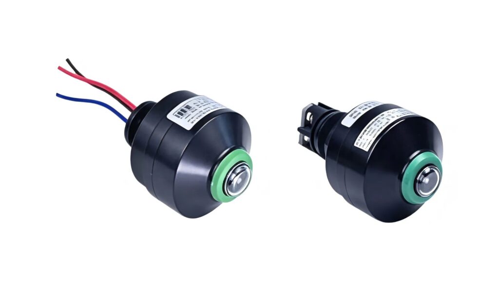
The public MMAIATEX About page states that ATEX, IECEx and CCC certification work is in progress. MMAIATEX Explosion-proof Technology (Zhejiang) Co., Ltd. does not present this guide, an entity inequality, a circuit sketch, a product category or a representative photograph as proof that a particular model or intrinsically safe system is certified.
Verify the exact legal manufacturer, model, terminals, complete marking, current certificate status and scope, schedules, control drawings, instructions and project requirements before selection or use.
Safety and legal disclaimer
This guide is educational and provides only a first-screen workflow. It does not design, calculate, certify or approve an intrinsically safe system, classify a hazardous area, validate functional safety or replace a competent assessment using the licensed current standards, exact product documentation and applicable law.
Request an intrinsically safe loop evidence review
Send the loop drawing, exact barrier or isolator, field-device identities, certificate issues, control drawings, entity values, cable type and length, earthing method, destination and hazardous-area requirements. MMAIATEX can identify available product records for review by the responsible engineering and compliance team.