
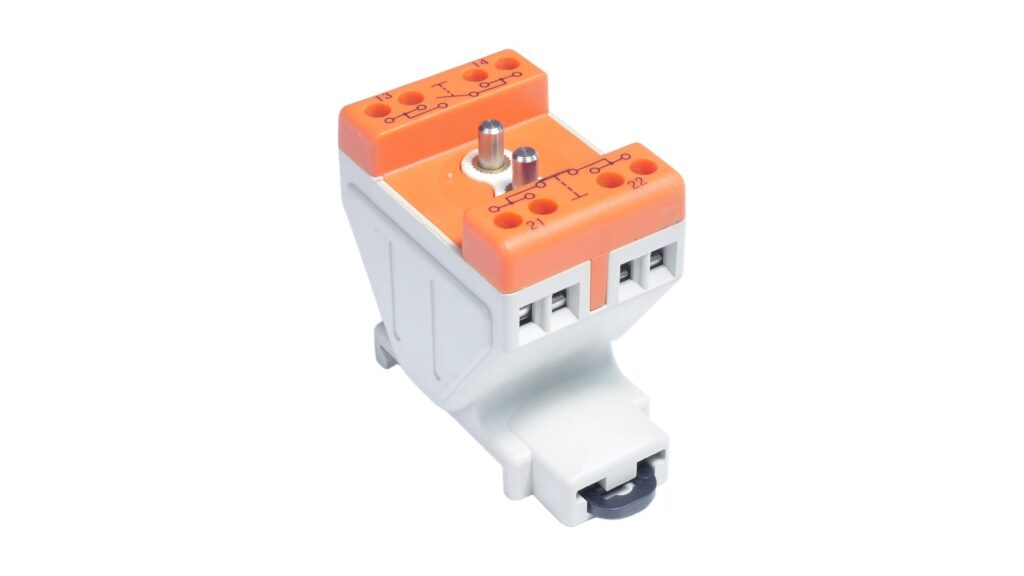
13-14 vs 21-22 contact numbering at a glance
The two pairs usually describe different contact functions on an auxiliary or control contact block. Read the whole pair. A single number is not enough.
| Terminal pair | Conventional reading | State at the defined normal position | What still needs confirmation |
|---|---|---|---|
| 13-14 | First normally open contact element | Open | Exact device diagram, actuator position and model identity |
| 21-22 | Second normally closed contact element | Closed | Exact device diagram, actuator position and model identity |
In this convention, the first digit distinguishes the contact element. The final digits commonly identify the contact function: 3 and 4 for an NO pair, and 1 and 2 for an NC pair. This also explains why a different assembly may show 11-12 for a first NC contact or 23-24 for a second NO contact. Do not invent missing contacts from that pattern. Only numbers physically marked and documented for the exact device exist for the wiring decision.
The order of the two terminal numbers identifies a pair. It does not automatically establish current direction, supply polarity or which conductor should be treated as the source. Electronic modules, illuminated operators and monitoring circuits can add polarity or other constraints, so the product diagram remains decisive.
What normally open and normally closed mean
A normally open contact is open at the defined normal position and changes state when its operating mechanism is actuated as designed. A normally closed contact is closed at that defined position and opens when actuated as designed.
The important phrase is defined normal position. It is usually the unactuated reference position for an electromechanical control device, but it is not a universal description of the machine's operating state. It does not necessarily mean that the process is safe, the enclosure is open, power has been isolated or a coil is de-energised. Latching devices, assembled operators and mechanically linked devices need their own documented reference condition.
For a push button, selector switch, limit switch or relay assembly, confirm which physical or electrical condition the manufacturer uses for the diagram. The MMAIATEX panel-mount push-button FAQ and limit-switch FAQ explain why actuator arrangement and complete assembly evidence matter.
Which current IEC sources support the identification review
IEC 60947-5-1:2024 is Edition 5.0, published March 26, 2024. Its public scope covers electromechanical control circuit devices and switching elements used for controlling, signalling and interlocking. The page states limits of 1,000 V AC or 600 V DC for the devices within its scope. Those are scope ceilings, not ratings for the photographed contact block or any offered model.
IEC 60947-1:2020 is Edition 6.0, published April 22, 2020. The current copy incorporates IEC corrigenda issued in December 2022 and April 2024. Its official preview identifies normative Annex L for terminal marking and distinctive numbers, including a section for auxiliary contacts on two-position switching devices. The free preview does not reproduce the complete marking table, so exact design and wiring work must use the licensed current document and the manufacturer's controlled product information.
The official IEC 60947:2026 series lists IEC 60947-1:2020 and IEC 60947-5-1:2024 as the current Part 1 and Part 5-1 publications as of this review. A catalogue stability date is a maintenance planning date. It is not an automatic product, certificate or installation expiry date.
A six-step check before wiring
1. Freeze the exact component identity
Record the legal manufacturer, complete model code, contact-block suffix, actuator or host device and quantity of each block. Similar colours and housings can contain different contact arrangements.
2. Read every physical marking
Photograph the complete terminal face and record all pair numbers, symbols and ratings. Check for damaged, obscured or duplicated labels. Never infer a terminal that is not visible because another device uses the same moulding.
3. Match the current contact diagram
Compare the marked pair with the diagram for the exact model and revision. The drawing should establish the normal reference position and the state change when the device is operated. If the diagram, datasheet and physical marking disagree, quarantine the item for clarification instead of choosing the most convenient interpretation.
4. Confirm the whole assembled mechanism
A removable contact block does not operate by itself. Confirm that its mounting position, actuator, mechanical travel, latching behaviour and any guard are the approved combination. The control-station buyer FAQ covers the wider evidence set for an assembled control station.
5. Check the electrical duty
NO or NC says nothing about permissible voltage, current, utilization category, switching capacity, load type, short-circuit protection or electrical endurance. Match the real control load and protective arrangement to the current product data. Do not copy a headline rating from a visually similar block.
6. Verify safely and record the result
Where project procedures permit continuity testing, a competent person should isolate the circuit, prevent re-energisation, prove the required safe condition and use suitable test equipment. Test the documented normal and operated positions. A continuity result is useful commissioning evidence, but it does not replace the product drawing, conformity evidence or required inspection record.
What 13-14 and 21-22 cannot prove
The terminal numbers do not prove direct-opening action, mechanically linked or mirror contacts, an emergency-stop function, a safety category, Performance Level, SIL capability or diagnostic coverage. An NC contact is not automatically a safety contact. The emergency-stop buyer FAQ explains the additional function and evidence checks for that application.
The numbers also do not prove hazardous-area protection. A contact block may form part of a larger certified assembly, but 13-14 or 21-22 is ordinary circuit identification rather than an Ex marking. IEC 60079-0:2026 covers general construction, testing and marking requirements for Ex Equipment and Ex Components. IEC 60079-14:2024 covers selection, installation and initial inspection within its scope.
For a hazardous-area purchase, compare the exact complete equipment marking, certificate and schedule, approved internal components, enclosure, cable entries, ambient range and instructions. Use the MMAIATEX Ex-marking guide and certificate-verification guide as separate evidence checks. A photograph of a numbered block cannot establish any of them.
Buyer and commissioning checklist
- exact manufacturer and full model code;
- complete terminal numbers and contact diagram;
- documented normal reference position;
- required NO and NC sequence for the control logic;
- actuator, host assembly and mounting position;
- voltage, current, load type and utilization category;
- short-circuit protective arrangement;
- continuity test record where authorised;
- complete Ex marking and current certificate evidence where applicable; and
- approved drawing revision and change record.
Current MMAIATEX certification status
The public MMAIATEX About page states that ATEX, IECEx and CCC certification work is in progress. MMAIATEX Explosion-proof Technology (Zhejiang) Co., Ltd. does not present this guide, terminal numbering, a continuity result, a representative image or a product category as proof that a particular model or assembly is certified.
Verify the exact legal manufacturer, model, contact diagram, complete marking, current certificate status and scope, schedules, instructions and project requirements before selection or use.
Safety and legal disclaimer
This article is buyer education, not a wiring instruction for an unidentified device, control-logic validation, functional-safety assessment, hazardous-area classification, certificate decision or legal opinion. Competent project parties must apply the licensed standards, exact product drawings, current conformity evidence, site procedures and law that govern the actual assembly.
Request a contact-arrangement evidence review
Send the exact model code, terminal photograph, contact diagram, actuator or host assembly, required control sequence, load data, destination and hazardous-area requirement where applicable. MMAIATEX can identify available product records for review by the responsible engineering and compliance team.
Primary sources
- IEC 60947-5-1:2024
- IEC 60947-1:2020
- Official IEC 60947-1:2020 preview, used only to confirm the published contents structure for normative Annex L
- IEC 60947:2026 series
- IEC 60079-0:2026
- IEC 60079-14:2024